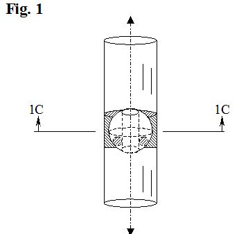
FIG. 1 is a diagrammatic cutaway perspective
view of a vertically orientated pendulous flow control valve system having a
rotatable weighted control valve and a tubular conduit.
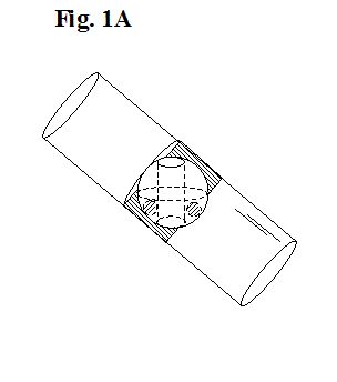
FIG. 1A is a diagrammatic cutaway perspective view of the flow control valve
system of FIG. 1 showing a left tilted, partially closed tubular conduit.
The various embodiments of a Pendulous Control Valve System, as detailed in the original US patent #7,334,596, and in the US Divisional Patent #7,504,599, are gravity operated control valves that allow the passage of either a low pressure gas or liquid, or an electric current, or an electromagnetic beam when the valve is vertical, and which occlude such passage when the valve is tipped.
A Pendulous Control Valve System of the type under consideration for relatively low pressure, small-scale applications, uses a caged rotatable ball valve having either internal or external gravity responsive masses and a vertically orientated axial conduit for flow control.
A Pendulous Control Valve System may be employed within a variety of small-scale flow applications that require a tilt-responsive on-off switching mechanism for allowing or preventing the flow of a low pressure gas or liquid. For example, for use in a diving or floating snorkel application as opposed to, say, an air pump application, or for use in a small water container application as opposed to a high pressure plumbing application.
In alternate embodiments, a Pendulous Control Valve System can be utilized to allow or interrupt the flow of an electromagnetic beam, for example, for use in a simple motion detector or plumb line application as opposed to, say, a missile guidance application. In another alternate embodiment, a Pendulous Control Valve System can be utilized to allow or interrupt the flow of an electrical current, for example, for use in a floor lamp tip-over application, as opposed to, say, an electrical distribution application.
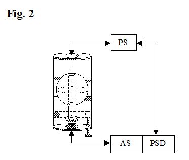
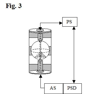
FIG. 2 is a diagrammatic cutaway perspective view of a vertically orientated
flow control valve system for controlling a light beam wherein annular support
rings and an external pendulous conduit are utilized.
FIG. 3 is a diagrammatic cutaway perspective view of a vertically orientated
control valve system for controlling an electric current.
SUMMARY
A housing containing a rotatable cage for rotatably supporting a spherical flow
control valve typically having a vertically orientated open or filled conduit
and an internal bottom weight mass centered on the vertical conduit. If the
rotatable cage is tilted, the gravity-responsive bottom weight mass rotatably
maintains the control valve conduit in a vertical orientation. If the cage is
walled, the rotating cage wall will travel over the ends of an open conduit to
form a seal, which effectively occludes any gas or liquid or electromagnetic
beam flowing through the conduit. If the cage is open and rotatably supports the
valve via annular supports, the rotating cage will effectively interrupt an
electromagnetic beam or electric current flow through the control valve conduit.
The flow control valve may also have a downwardly extended open or filled
pendulous conduit which may be provided with an additional weight mass.
Alternately, a pendulum with an open or filled conduit may have a magnetic
weight mass which can be captured by a provided lower metal ring to lock the
control valve system in an off position until the magnetic lock is released. A
locking ring may be alternately provided with a solenoid-operated release
mechanism for remote unlocking and resetting purposes. The invention may further
have a secondary electrically operated power-disconnect system, which serves to
shut down the overall flow system when the control valve conduit is occluded or
interrupted.
OBJECTS AND ADVANTAGES
The primary object of the invention of a Pendulous Control Valve System is to
provide a rotatably supported flow control valve that immediately closes in
response to a predetermined tilt angle of its cage enclosure. It is a further
object of the invention to provide a flow control valve that may be easily
modified for a variety of applications to serve as a tilt valve for respectively
occluding the flow of a gas or liquid, or to interrupt the passage of a light
beam or an electric current.
It is a still further object of the invention to provide a rotatable spherical
valve with an axial conduit and an internal bottom weight mass so that the valve
will remain in or restore itself to a gravity referenced vertical orientation
and to occlude or interrupt any flow through the conduit during any relevant
rotational displacement from vertical. It is also an object of the invention to
provide a secondary, electrically operated power-disconnect system for a control
valve application, when required, which serves to shut down the overall power
source of the flow system application when a control valve conduit is occluded
or interrupted.
An example of an object of a Pendulous Control Valve System being utilized as a
low pressure gas flow control valve in a larger order, but still small scale
application, would be for use with diving or float suspended snorkels to prevent
the introduction of water into the air intake of a snorkel by closing the air
intake as the snorkeler tilts the snorkel to dive. An example of an object of a
Pendulous Control Valve System being utilized in a larger order, but still small
scale application as a liquid control flow valve would be as a shut-off valve in
a portable water supply system which overturns. An example of an object of a
Pendulous Control Valve System utilized as an electric current flow control
valve in a larger order, but still small scale application, would as a shut-off
switch for a floor lamp which overturns. An example of an object of a Pendulous
Control Valve System utilized as an electromagnetic beam flow control valve in a
larger order, but still small scale application, would be as a beam interrupter
for a photocell in an alarm system.
It is still a further object of this invention to provide a Pendulous Control
Valve System that serves the above listed purposes and other similar purposes,
and is also relatively simple to manufacture and to use, reliable during use,
durable, and fabricated from inexpensive, commonly available materials.
The primary advantage of a Pendulous Control Valve System is that it combines a
number of possible functional features and abilities in one relatively compact
and simple device, all of which possible functional features and abilities are
useful in association with practical activities. A further advantage is that a
Pendulous Control Valve System provides a flow control valve that immediately
closes in response to a predetermined angular tilting of its enclosure in any
direction. It is a also a further advantage of the invention that it provides a
simple flow control valve which may be respectively utilized to interrupt the
flow of a gas or a liquid, or to interrupt the passage of an electromagnetic
beam or an electric current.
There is a clear need for a Pendulous Control Valve System for low pressure,
small scale applications, which is durable, simple to use, reliable during use,
and which is fabricated from inexpensive commonly available materials and
components, and which is relatively easy to manufacture, maintain, and repair.
Other objects and advantages of the invention will become clear upon review of
the detailed description and accompanying drawings in the patents indicated
below.
Patent Abstract
Or Click
here to
download a copy of Patent #7,334,596
Divisional Patent for Electric Current Claims
Or Click here to download a copy of Patent #7,504,599
Email: JixisGMS@aol.com
![]()